Tech Tips: Ball Detect Repairs/Returns and Adjustment
Over the years, Brunswick has made continuous improvements to the original, adjustable head ball detect unit used on GS pinsetters and with some scoring system cameras and scanners. It is possible that the ball detect unit you send in for repair, may be returned to you with subtle differences. Although we will make every attempt to return the same style, vintage and configuration of ball detect to you – there may be times when, due to changes in manufacturing or availability of replacement parts, the unit you receive back may not look exactly like the unit you sent in. The unit you receive will still be compatible with your system.
NOTE: Other ball detectors such as the dual ball detect units that accommodate signals for scoring and pinsetters in the same housing and the round Vector scorer ball detects are not the subject of this Service Bulletin.
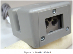
Brunswick now offers the ball detect only as a repaired assembly – a single head mounted and adjusted in an enclosure. Part number for this version is 99-086292-800. Refer to Figure 1.

This is the most logical configuration of the ball detect, as it comes to you tested and pre-adjusted. You should be able to remove your failed unit and install the replacement on the mounting bracket with minimal (if any) adjustment required. (Refer to the adjustment at the end of this bulletin).
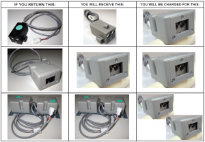
On occasion, we have returns that do not match this configuration. The following table contains information on how the return and billing will be handled, going forward.

If you need ball detects pre-shipped to your center, that can be done for an additional service fee. It is important that you return the same configuration ball detect as what you ordered. We recommend that you keep this Service Bulletin handy for future reference when ordering a pre-ship from your repair/exchange depot.
It is also important to note that well over 50% of the returned ball detects have “no problem found” when we receive them and the majority are simply out of adjustment. Following is a ball detect adjustment procedure that will help you to ensure your ball detect is properly adjusted.
Ball Detect Adjustment
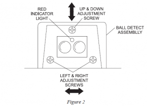
The ball detect assembly uses an infrared light which cannot be seen without an optical aid. Therefore, it has a red indicator light on the face of the unit that will light when insufficient infrared light is reflected back to it. Refer to Figure 2.

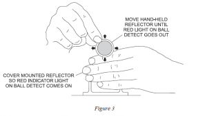
To center the infrared beam on the reflector, use the following steps. Refer to Figure 3.
1. With power on to the pinsensor, cover the reflector mounted on the division capping so the red indicator light on the ball detect unit comes on.
2. Using another hand-held reflector, start above the covered reflector and slowly move the hand-held reflector down toward the covered reflector while holding it square to the ball detect unit. Continue to move the hand-held reflector until the red light goes out and note the position of the hand-held reflector.

3. Repeat the same procedure starting below the covered reflector (in the ball gutter) and move the hand-held reflector up until the light goes off and note that position.
4. Repeat the same procedure starting from the left of the covered reflector and then from the right until you have located the relative position of the infrared beam.
5. If the beam is not centered on the covered reflector, it can be adjusted with the three adjustment screws in the face of the unit. The top screw moves the beam up and down. A clockwise turn moves the beam down while a counterclockwise turn will move it up. Refer to Figure 2.
6. The side screws will move the beam left to right. Refer to Figure 2.
7. After each adjustment, recheck the beam’s location with the hand-held reflector following the procedure detailed above.
Should you have any further questions, don’t hesitate to contact us!